PRESSURE ROLLERS
PRESSURE ROLLERS
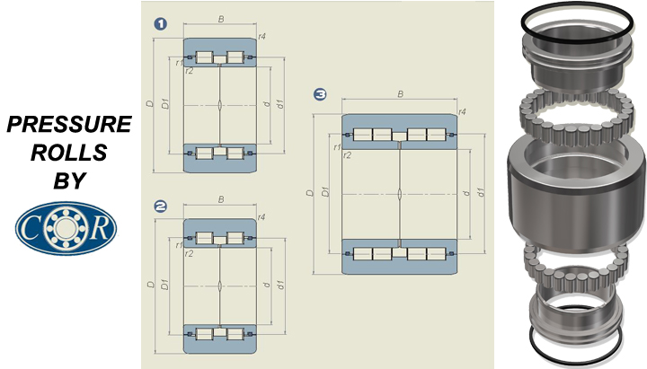
| Part Number | d (mm) | d1 (mm) | D (mm) | D1 (mm) | B (mm) | r1,2 (mm) | Design Type | C (kN) | Co (kN) | Cw (kN) | Cow (kN) | |
|---|---|---|---|---|---|---|---|---|---|---|---|---|
| 900-2340 | 93 | 126 | 170 | 127 | 95 | 2 | 10x15° | 1 TB2 | 429 | 655 | 286 | 390 |
| 900-3852 | 100 | 148 | 200 | 149 | 114 | 4 | 10X15° | 1 TB2 | 605 | 1000 | 413 | 600 |
| 900-3853 | 105 | 151 | 215 | 153 | 87 | 3 | 3 | 2 TB1 | 501 | 695 | 358 | 450 |
| 900-2339 | 110 | 157 | 210 | 158 | 110 | 2 | 10X15° | 1 TB2 | 402 | 610 | 255 | 325 |
| 900-2818 | 120 | 157 | 210 | 158 | 114 | 4 | 10X15° | 1 TB2 | 550 | 915 | 330 | 455 |
| 900-3854 | 128.665 | 160 | 210 | 162 | 114 | 4 | 10X15° | 1 TB2 | 583 | 1120 | 352 | 560 |
| 900-3855 | 140 | 178 | 250 | 180 | 110 | 3 | 11.5X17° | 1 | 825 | 1400 | 561 | 850 |
| 900-3446 | 140 | 187 | 250 | 188 | 114 | 3 | 13.5X17° | 1 | 825 | 1400 | 512 | 750 |
| 900-3856 | 140 | 187 | 280 | 188 | 114 | 3 | 13.5X15° | 1 TB1 | 913 | 1460 | 671 | 1000 |
| 900-3857 | 160 | 195 | 250 | 197 | 140 | 3 | 13.5X17° | 3 TB1 | 2120 | 4400 | 1100 | 1830 |
| 900-3858 | 160 | 231 | 320 | 233 | 120 | 4 | 13X17° | 1 | 1140 | 2040 | 737 | 1140 |
| 900-3859 | 160 | 227 | 330 | 228 | 140 | 4 | 6.5X15° | 1 | 1140 | 2040 | 825 | 1340 |
| 900-3860 | 180 | 238 | 330 | 240 | 125 | 4 | 6.5X15° | 1 | 968 | 1930 | 644 | 1100 |
| Symbol | Definition |
|---|---|
| C | Dynamic Load as Bearing |
| Co | Static Load as Bearing |
| Cw | Dynamic Load as Roller |
| Cow | Static Load as Roller |
| TB1 | bainitic temper of inner and outer ring |
| TB2 | bainitic temper of outer ring |