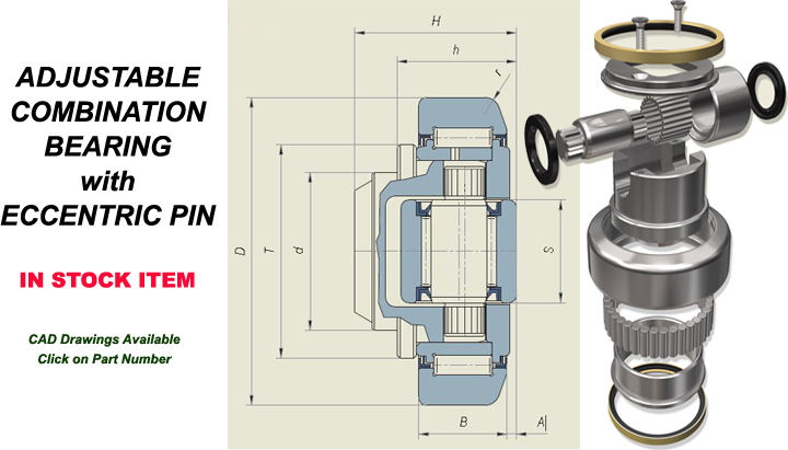
Home→Combination Bearings→Adjustable Combination Bearings with Eccentric PinAdjustable Combination Bearings with Eccentric PinAdjustable Combination Bearings with Eccentric PinPrinter Friendly Version Bearing Selection GuidePart NumberD (mm)T (mm)d (mm)H (mm)h min-max (mm)B (mm)A (mm)S (mm)r (mm)C (kN)Co (kN)Ca (kN)Coa (kN)Wt (kg)Profile Type4.45462.5423037.530.5-32204203396516250.5328904.45570.148354436-37.5234204569316250.8028674.4567854404837-38.5233.52645910223361.0028104.45778.354404029.30.5233.52645910223360.8730194.45888.459455744-44.53042648513423361.6228114.459101.669504633-35264.53039114032501.7434404.460108.569555440-4231430510017432502.2731004.461107.769606955-5731430510017432502.2828624.462123806072.356-60374.534513524241723.6028914.463149.41086078.558.5-62.545634318335341726.302757 Adjusting ProcedureSymbolDefinitionCDynamic LoadCoStatic LoadCaAxial Dynamic LoadCoaAxial Static LoadNote: Bearings have much higher load ratings than corresponding guide rail profiles. Always make selections based on Hertzian pressure calculations of the rails.